Kulfan canvas
Every section on this site is stored as a handful of numbers, not as points, and the canvas is where you can see and move them. Load a library section, a .dat file or a NACA code, drag a weight and watch the shape and its figures follow, then export it at the chord your rib or mould needs. Nothing here is metered, and nothing you do changes the library.
Transcript
- Under Load foil from database, type the name and click Load.
- Chord (mm) sets the size the DXF is drawn at: 145 mm, the freeride foil's root.
- DXF writes one cubic spline per surface at that chord. Change the number and export again for another station.
What CST is
The Class-Shape Transformation (Kulfan, 2008) writes each surface as a class function times a shape function, plus a trailing-edge term:
y(x) = x^N1 · (1 − x)^N2 · S(x) ± x · TE/2
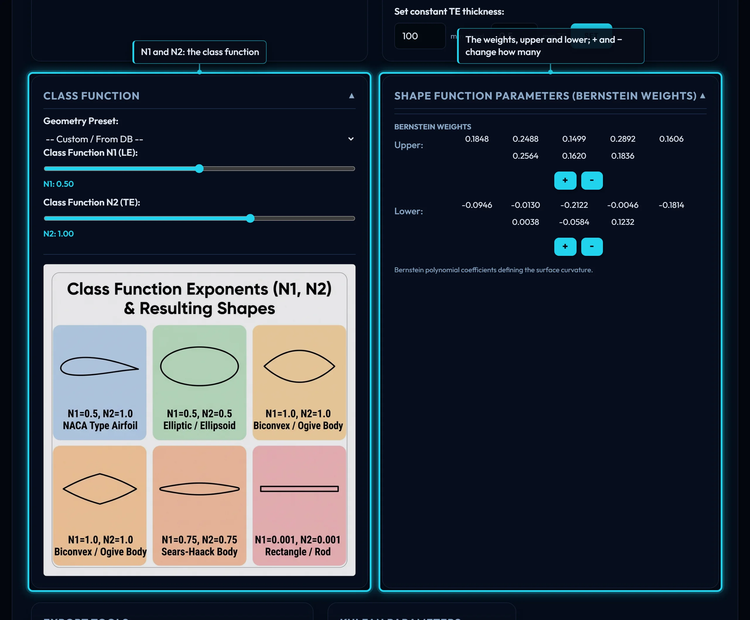
The class function fixes the kind of body; the shape function S(x), a sum of Bernstein polynomials with one weight each, carries everything that makes one section differ from another. Each surface has its own weights and a leading-edge weight is added to both. That is the whole parameter set the foil page shows in its read-only box.
The class function
N1 and N2 are the two exponents: 0.5 at the nose gives the square-root start every round-nosed section has, 1 at the tail closes it to a sharp edge. Every library section and NeuralFoil's training use those values, so any other pair draws here but cannot be analysed or optimized. The other presets are bodies that are not aerofoils.
Geometry Preset is a fresh start, not an edit: it sets N1 and N2 and overwrites every weight to ±0.15, with the leading-edge weight, TE thickness and both scalars reset.
The Bernstein weights
Transcript
- Any library section loads as its CST parameters: two class exponents, a leading-edge weight, a trailing-edge thickness and a row of Bernstein weights per surface.
- Each weight bends one span of its surface; thickness and camber are measured from the drawn curve as you edit.
- A geometry preset overwrites every weight, so set the class exponents first and the weights after. Export the result as DAT or DXF, or send it to a wing.
Each weight scales one bump along the chord; with n + 1 weights the i-th bump peaks at i/n. The first sets the nose radius, the last the angle the surface leaves the trailing edge at. Upper weights are positive, lower negative. + and − append or drop the last weight on a surface, down to 2; the library, the .dat fit, NeuralFoil and the optimizer all use 8 per surface.
Shape Function Plot draws the two shape functions under the section; a weight moves a bump there. Symmetry forces every lower weight to minus its upper weight, the leading-edge weight to 0 and N1, N2 to 0.5, 1; a section loaded while it is on is symmetrised.
The leading edge and the trailing edge
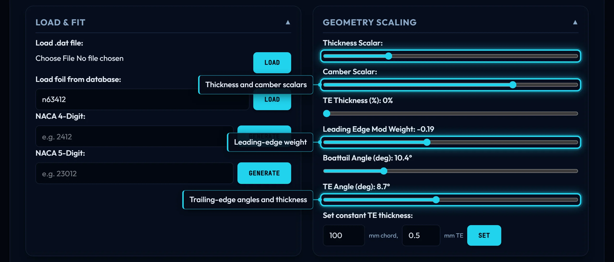
Leading Edge Mod Weight adds the same bump, w · x · (1 − x)^(n + 1.5), to both surfaces: it bends the mean line just behind the nose without changing the thickness there, the one thing the weights alone do badly.
TE Thickness is the trailing-edge gap as a percentage of chord, up to 2 on the slider, added half to each surface and growing linearly from the nose. Set constant TE thickness does the sum from a gap in millimetres at a chord in millimetres, rounded to 0.01 % of chord and capped at the slider's maximum. Both exports carry the gap; there is no separate box for it.
Boattail Angle is the half-angle the surfaces close at; dragging it writes ± the same value into the last weights. TE Angle is the angle of the mean line at the trailing edge; dragging it shifts both last weights together, turning the tail without changing its wedge.
The scalars
Each weight pair splits into a thickness half, (upper − lower)/2, and a camber half, (upper + lower)/2. Thickness Scalar multiplies the first, Camber Scalar the second: 1 is the section as loaded, a camber scalar of 0 makes it symmetric, a negative one inverts it. Loading a section sets both to 1. Exports and every hand-off apply the scalars; the parameter box shows the raw weights.
Loading a section
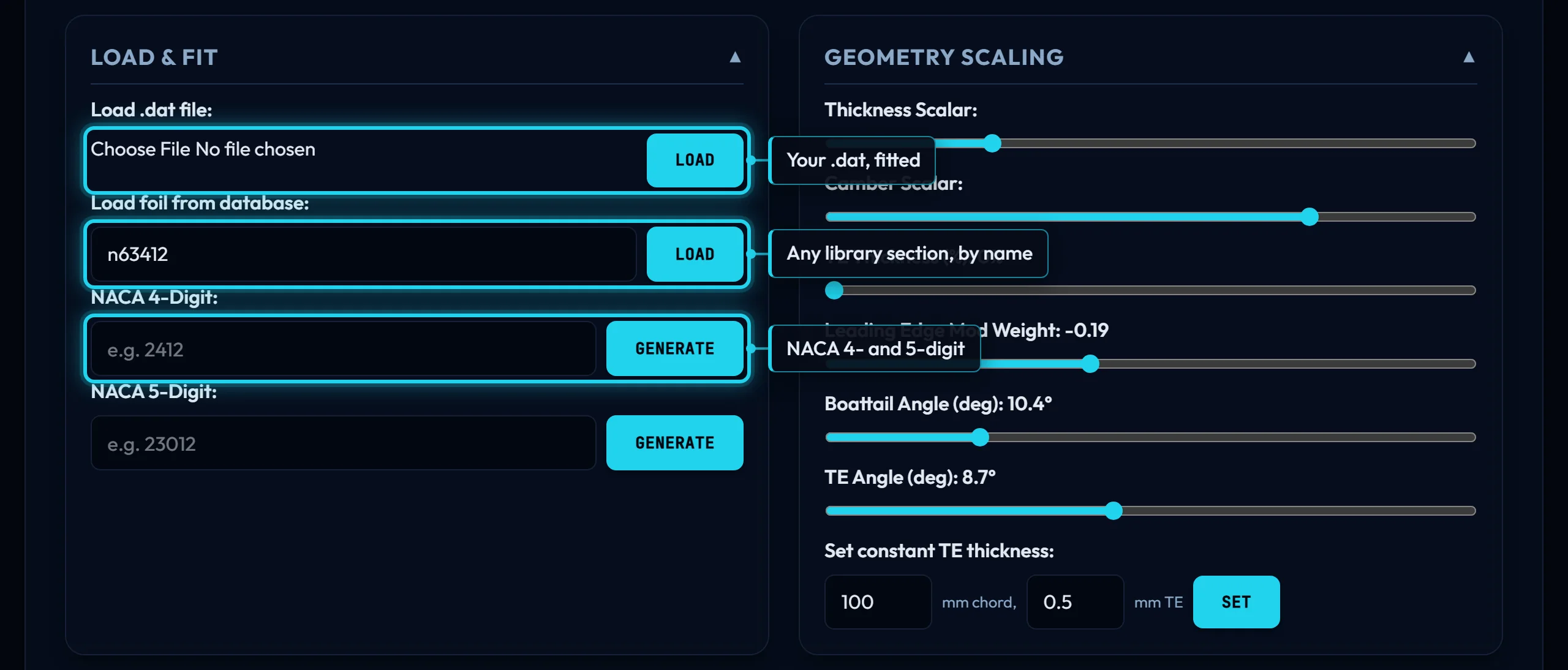
- Load foil from database loads any library section's stored parameters, as its page draws them.
- Load .dat file fits 8 weights per surface plus the leading-edge weight by least squares at the current N1 and N2: Selig order, normalised to unit chord, the gap read from the end points (File formats has the reader's rules).
- NACA 4-Digit and 5-Digit generate the section from the NACA formulas and fit the weights to it, closely rather than exactly; 5-digit does the normal series only.
- Reset to DAE-11 puts back the section the page opens with;
?foil=n63412opens any library section instead.
The readouts
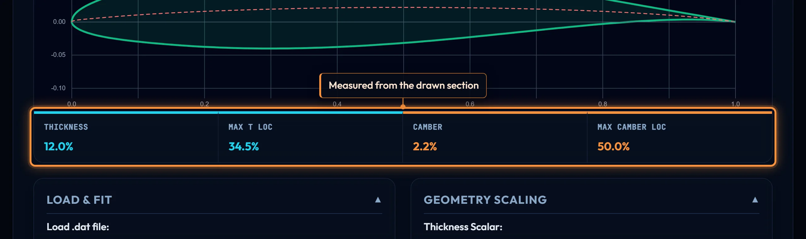
The four figures above the controls are measured from the drawn section with the scalars applied: maximum thickness and camber and where each sits, as percentages of chord. They are the foil page's figures, read from the curve the exports write.
Exports and the chord
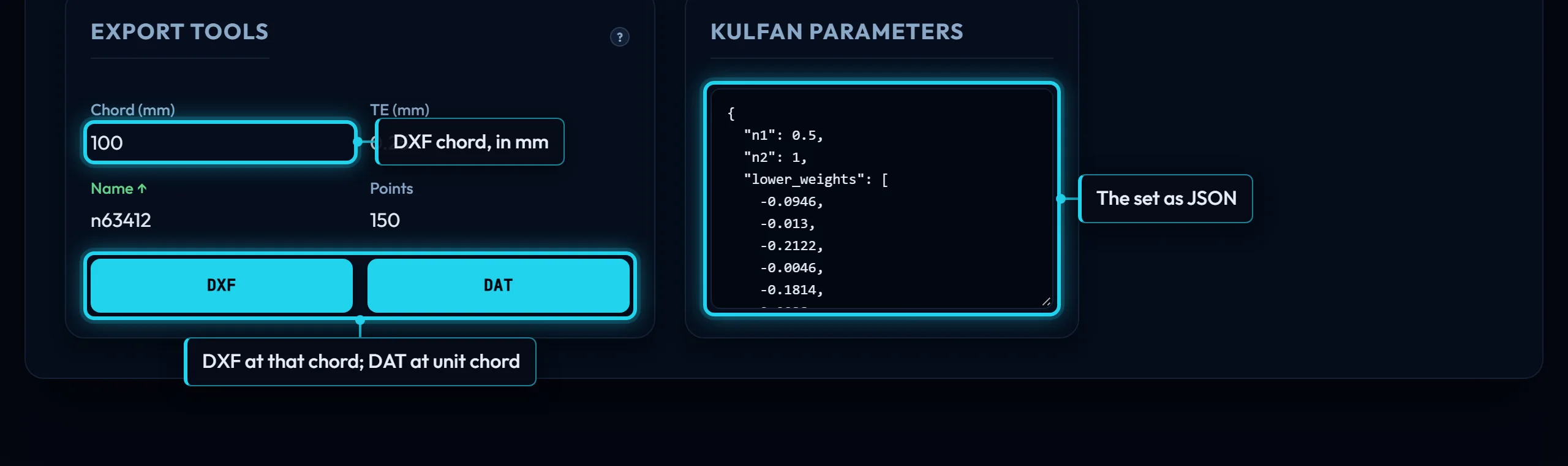
DXF draws the section at Chord (mm), so it lands in CAD at the size of the part: 100 by default, or the 145 mm root chord of the running example for a rib template with no scaling step. DAT is always at unit chord, in Selig order, with the Name box as its first line; Points is the number of lines in the file in total, both surfaces with the leading edge written once, so 150 gives 76 per surface. Both files carry the scalars and the gap. The name box mirrors the NAME box at the top of the page, which is what the arrow points at; File formats describes both files.
Kulfan Parameters is the parameter set as JSON, scalars not folded in: what the API and the optimizer take as starting_params.
What this hands on
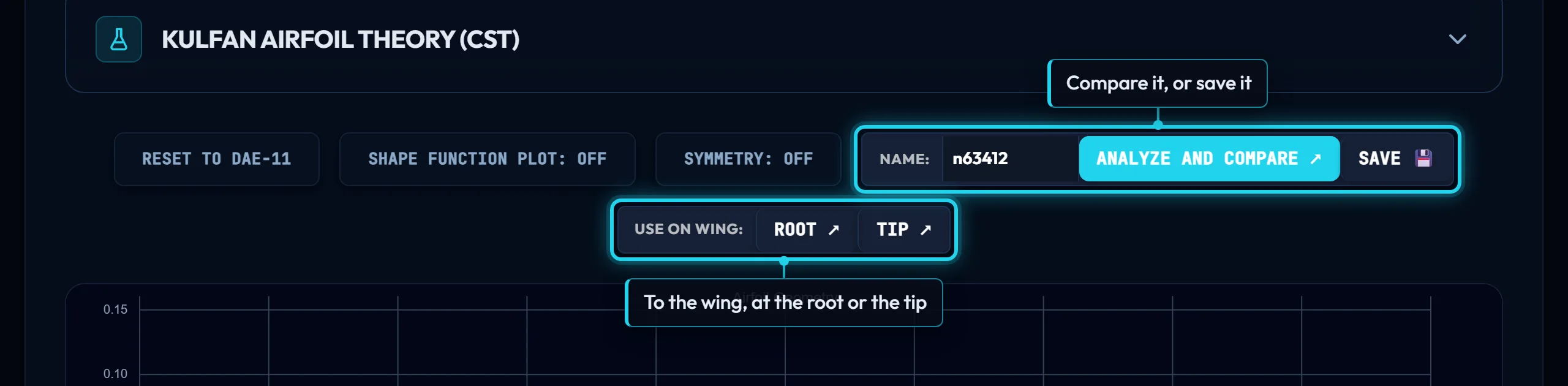
An edited section goes three ways, scalars applied, under the name in the box. Analyze and Compare runs its polars on Compare. Root or Tip opens the wing designer with it in that slot, where Sections along the span takes over. Save puts it in your account, to reopen here or place on a wing later. Or export it: the DXF for the shop, the DAT for XFLR5 or OpenVSP.
Controls on this page
| Control | What it does | Units |
|---|---|---|
| Load .dat file | Fits 8 weights per surface plus the leading-edge weight to a Selig-order .dat by least squares, at the current N1 and N2. The chord is normalised first and the trailing-edge gap is read from the file's end points. | |
| Load foil from database | Loads a library section's stored CST parameters, exactly as its page draws them, and resets both scalars to 1. Type a name; the list offers every section in the library. | |
| NACA 4-digit | Generates the section from the NACA formulas (camber, its position, thickness) and fits the weights to it at N1 0.5 and N2 1. The fit is close, not exact: the NACA thickness form is not a Bernstein sum. | |
| NACA 5-digit | The same fit for a 5-digit code. Normal series only: a reflexed code (third digit 1) is drawn with the normal camber line and says so. | |
| Reset to DAE-11 | Puts back the section the page opens with, the DAE-11, and turns symmetry off. Open the page with ?foil=<name> to start from any library section instead. | |
| Shape Function Plot | Draws the two shape functions under the section: the weighted Bernstein sum for each surface, before the class function shapes it. A weight moves a bump in this plot; the section follows. | |
| Symmetry | On, every lower weight is forced to minus its upper weight, the leading-edge weight to 0, and N1 and N2 to 0.5 and 1. Moving the TE angle or generating a cambered NACA turns it off; a section loaded while it is on is symmetrised. | |
| Thickness Scalar | Multiplies the thickness half of every weight pair, (upper − lower)/2, leaving the camber half alone. 1 is the section as loaded. Exports and hand-offs carry it; the parameter box does not. | |
| Camber Scalar | Multiplies the camber half of every weight pair, (upper + lower)/2. 1 is the section as loaded, 0 makes it symmetric, negative inverts it. Loading a section sets it to 1; the page opens at 0. | |
| TE Thickness | The trailing-edge gap as a percentage of chord, up to 2. Half is added to the upper surface and half taken from the lower, growing linearly from the nose, so only the tail moves. Both exports carry it. | % chord |
| Leading Edge Mod Weight | Adds the same bump, w·x·(1−x)^(n+1.5), to both surfaces, so it bends the mean line just behind the nose without changing the thickness there. Positive raises both surfaces behind the nose; symmetry forces it to 0. | |
| Boattail Angle | The half-angle the two surfaces close at. Dragging it writes the last upper weight and minus that value into the last lower weight, so the trailing edge becomes symmetric about the chord line at that angle. | deg |
| TE Angle | The angle of the mean line at the trailing edge, positive downward. Dragging it shifts both last weights by the same amount, which turns the tail without changing its wedge, and switches symmetry off. | deg |
| Set constant TE thickness | Converts a gap in mm at a chord in mm into the TE Thickness slider: the result is rounded to 0.01 % of chord and capped at the slider's 2 %. 0.5 mm on a 100 mm chord is 0.5 %. | |
| Geometry Preset | Sets N1 and N2 for a named class of body and overwrites every weight to ±0.15, with the leading-edge weight, TE thickness and scalars reset. It is a fresh start, not an edit of the loaded section. | |
| Class Function N1 | The exponent on x in C(x) = x^N1·(1−x)^N2: 0.5 gives a round nose, 1 a pointed one. Every library section, NeuralFoil and the optimizer use 0.5; other values draw but cannot be analysed. | |
| Class Function N2 | The exponent on (1−x): 1 closes the tail to a sharp edge, smaller values blunt it, 0.5 rounds it like an ellipse. Library sections and NeuralFoil use 1. | |
| Bernstein Weights | Each weight scales one Bernstein bump, centred at i/n along the chord; the first sets the nose radius, the last the tail angle. Upper weights are positive, lower negative. + and − add or drop a weight, down to 2. | |
| Thickness | Maximum upper-minus-lower distance of the drawn section, as a percentage of chord, with the scalars applied. Measured on the same points the exports use. | % chord |
| Max t/c Loc | Where along the chord the section is thickest, as a percentage from the leading edge. | % chord |
| Camber | The largest distance of the mean line from the chord line, as a percentage of chord. Negative when the mean line bows downward. | % chord |
| Max Camber Loc | Where along the chord the camber peaks, as a percentage from the leading edge. | % chord |
| Export Tools | DXF: the section at the chord in mm, for CAD. DAT: unit chord, Selig order, for XFoil, XFLR5 or OpenVSP. Both carry the scalars and the trailing-edge gap set by the TE Thickness slider; the DAT carries the name. | |
| Chord | The chord the DXF is drawn at, in millimetres, so it lands in CAD at the size of the rib or the mould. It does not affect the DAT, which is always at unit chord. Opens at 100. | mm |
| Name | The first line of the DAT and the file name of both exports. It mirrors the NAME box at the top of the page, which is why the arrow points there; a loaded section fills it in. | |
| Points | Lines in the DAT in total, both surfaces, the leading edge written once (10 to 1000). 150 gives 76 per surface, spaced closer at the nose and tail. The DXF has its own sampling. | |
| Kulfan Parameters | The parameters as drawn, as JSON: N1, N2, TE thickness, the leading-edge weight and the raw weights. The two scalars are not folded in; exports, Compare, the wing and Save apply them first. | |
| Analyze and Compare, Use on wing, Save | Each takes the section with the scalars applied, under the name in the box. Compare runs its polars; Root or Tip opens the wing designer with it in that slot; Save puts it in your account, from where it can be reopened here. |