File formats
Five files leave the site: DXF and DAT for a section, CSV for a polar, STEP and STL for a wing. One comes in: a DAT, on Compare and on the Kulfan canvas. This page says what each holds, in what units, and what reads it. Every description below was taken from the code that writes the file.
DXF
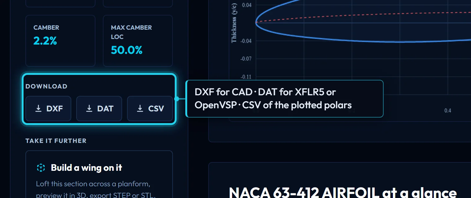
A section as a 2D drawing in millimetres, for CAD. The chord is set by the page: 1000 mm from a section page, Search, Mission's results, Compare and Optimize; on the Kulfan canvas it is the chord you type. Scale it in your CAD program if you need another.
What is in the file:
- Two cubic splines, one per surface, on layers
UPPERandLOWER. Each runs from the leading edge to the trailing edge through a dense sampling of the surface, denser near the nose. A control point is placed on the chord line at the leading edge so the two splines meet there with vertical tangents rather than a kink. - Reference points on layer
POINTS, a sparse set of the sampled coordinates from both surfaces, there to check the splines against if your CAD program resamples them. - A trailing-edge line on
POINTS, joining the two splines, only when the section has a blunt trailing edge. A sharp section closes at a point and gets no line.
The geometry is the drawn CST curve, the same one the viewer and the DAT carry, so the three agree. Fusion 360, Rhino, FreeCAD, SolidWorks and most 2D CAM programs read it; if yours draws the splines as polylines, the POINTS layer is the original data.
DAT
Selig-format coordinates at unit chord, the form XFLR5, XFoil, OpenVSP, AeroSandbox and most other tools read.
- Line 1 is the section name.
- Then one point per line,
x ywith six decimals, from the trailing edge forward over the upper surface to the leading edge and back along the lower surface to the trailing edge. The leading edge point is written once. - 151 points from a section page, Search, Mission's results and Compare. The Kulfan canvas writes the count you type. Optimize writes a denser file of the optimized shape.
A blunt trailing edge appears as the first and last points having different y at x = 1.
Uploading a DAT
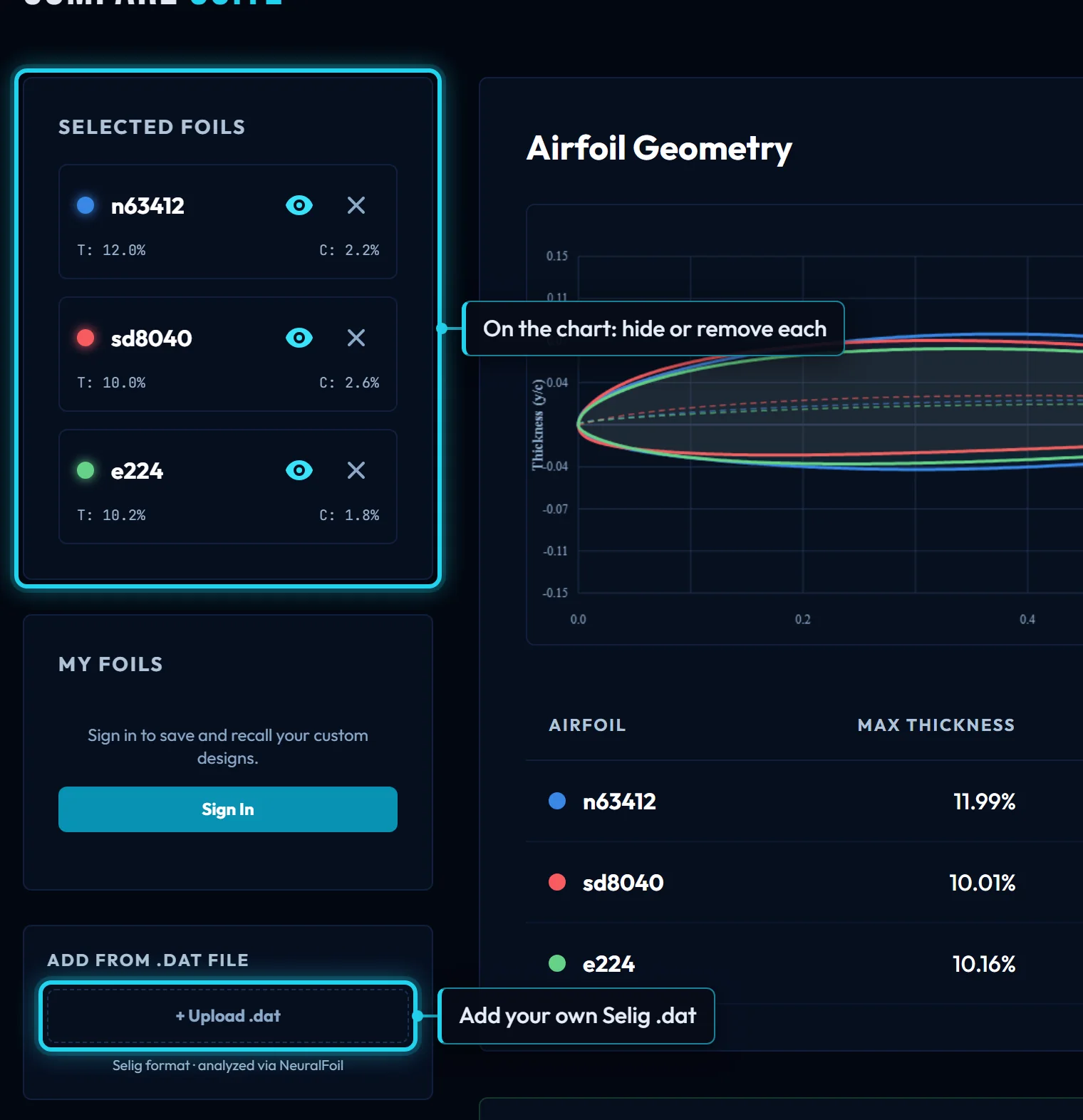
Compare takes a .dat file and overlays it with the library; the Kulfan canvas fits CST parameters to one so it can be edited. Both read it the same way:
- Any line that is two numbers is a point; everything else, including the name line, is skipped.
- The chord is normalised:
xis shifted to start at 0 and both axes are divided by the chord, so a file at 250 mm reads the same as one at unit chord. - The file is split at its midpoint into the two surfaces, so it must be in Selig order with the surfaces of similar length. A Lednicer file (two blocks, each from the leading edge, with a count line) is not read correctly; convert it first.
CSV
Two pages write a polar as CSV. Both are plain text, one header line, one row per angle of attack, no units column: angles in degrees, coefficients dimensionless.
- A section page writes what the chart draws: the ticked Reynolds numbers at the selected Ncrit, stored rows and live runs alike, columns
Re,Ncrit,alpha,CL,CD,CM. The file name carries the section and the Ncrit, so two downloads at different Ncrit do not land as one file and its copy. Angle of attack runs -20° to 25° in 0.5° steps for a stored row. - Wing analysis writes the sweep of the last run, columns
alpha,CL,CD,CM,L_over_D, aswing_polar.csv. The coefficients are for the whole wing, referenced to the S_ref the panel reports.
STEP and STL
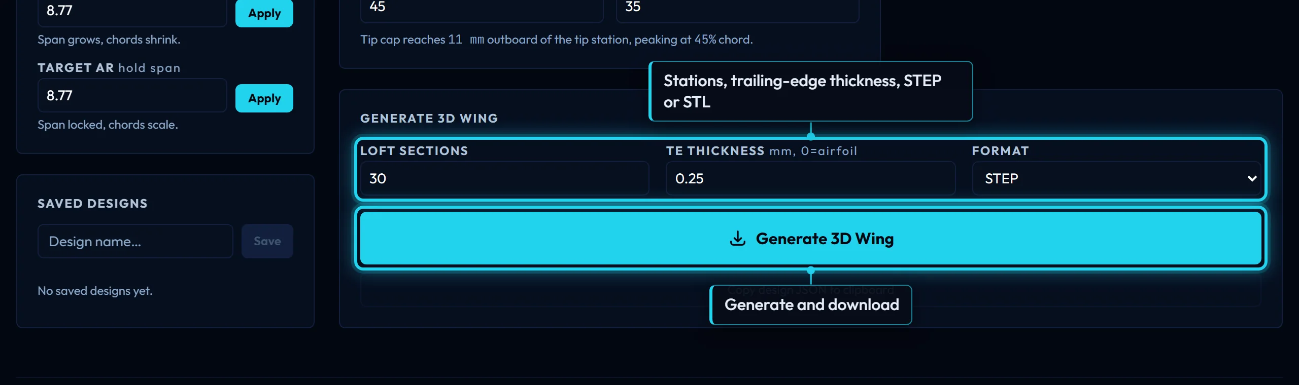
The wing designer exports the wing it draws. Both files are in millimetres and both hold the whole wing, both halves, as one closed solid: the half you edit lofted through the sections, then mirrored about the root.
- STEP is the exact loft, a B-rep surface through every station, for CAD. Open it in Fusion 360, Rhino, FreeCAD, Onshape or SolidWorks and it is a solid you can shell, split or cut moulds from.
- STL is the same solid as a triangle mesh, for slicers and mesh tools. The tessellation tolerance is the exporter's default, fine enough for printing at the sizes the designer allows; for machining, take the STEP.
What the loft contains:
- The stations are the section at each position along the span, blended from the root section to the tip section, placed on the leading and trailing edges you drew, twisted as the twist profile says. Loft sections, under Export, sets how many.
- The tip is flat unless Tip rondure is on, in which case a rounded cap continues the planform past the last station.
- The trailing edge is each section's own unless TE thickness, under Export, is set, in which case every station is opened to at least that. A wing that mixes a sharp section with a blunt one is lofted with every edge opened slightly, because the loft cannot take both.
Export needs a sign-in. The viewer and the file are the same loft, so what you see is what you get; where they can differ is the subject of the Wings pages on the docs index.