Twist, dihedral and the tip
With the outline and the sections set, three things remain that change the wing without changing its area: how the sections are rotated along the span, how the tips sit above or below the root, and how the tip is closed. The Wing Foil — Freeride carries -2° of tip twist, -2° of dihedral and a rounded tip with bias 45 % and reach 35 %. Each has its own canvas on the Design tab.
Twist and washout
Tip twist is the geometric angle of the tip section relative to the root, -15 to 10°. Negative is washout: the tip is rotated nose-down, flies at a lower angle of attack than the root, and reaches its stall later. The twist profile canvas draws the angle against span, zero at the root and the box's value at the tip; add a point and drag it to shape where the washout comes in. Every station is rotated by the curve's value there, in the viewer, the analysis and the export alike.
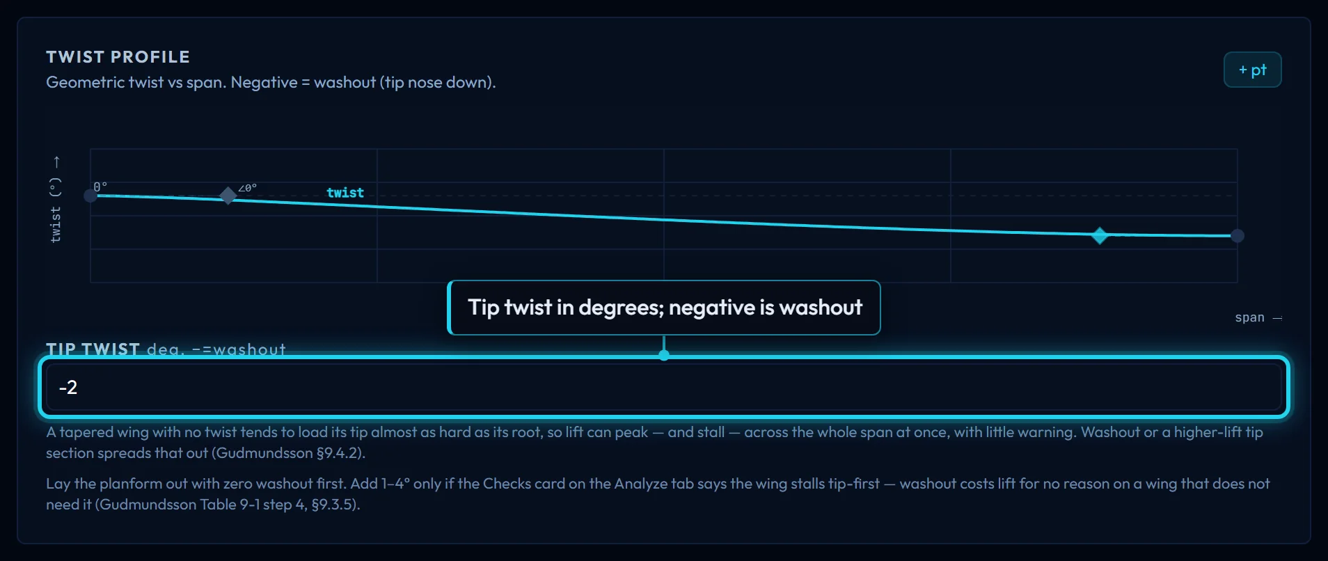
Lay the planform out with zero washout first. Add 1–4° only if the Checks card on the Analyze tab says the wing stalls tip-first: washout costs lift at cruise for no reason on a wing that does not need it, and a tapered wing with no twist is the one that tends to. A higher-lift tip section, on the previous page, spreads the stall the same way.
Transcript
- Tip twist is washout when negative: the tip flies at a lower angle than the root, so it is the last part of the wing to stall.
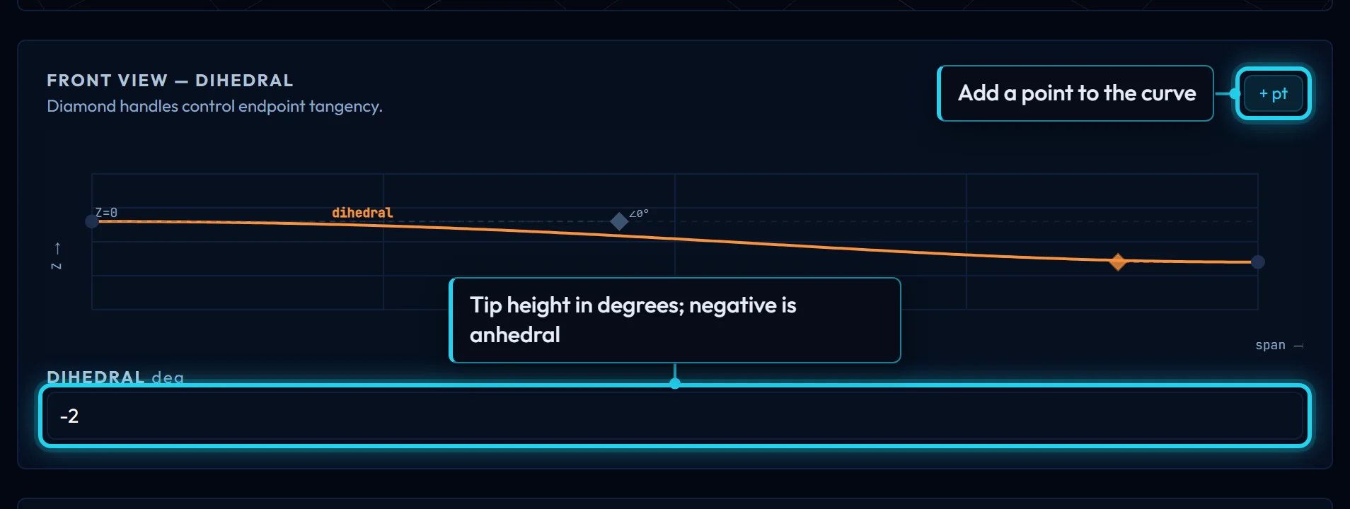
- Dihedral is negative on most hydrofoils: anhedral drops the tips, which helps the foil track and lets the tips breach later.
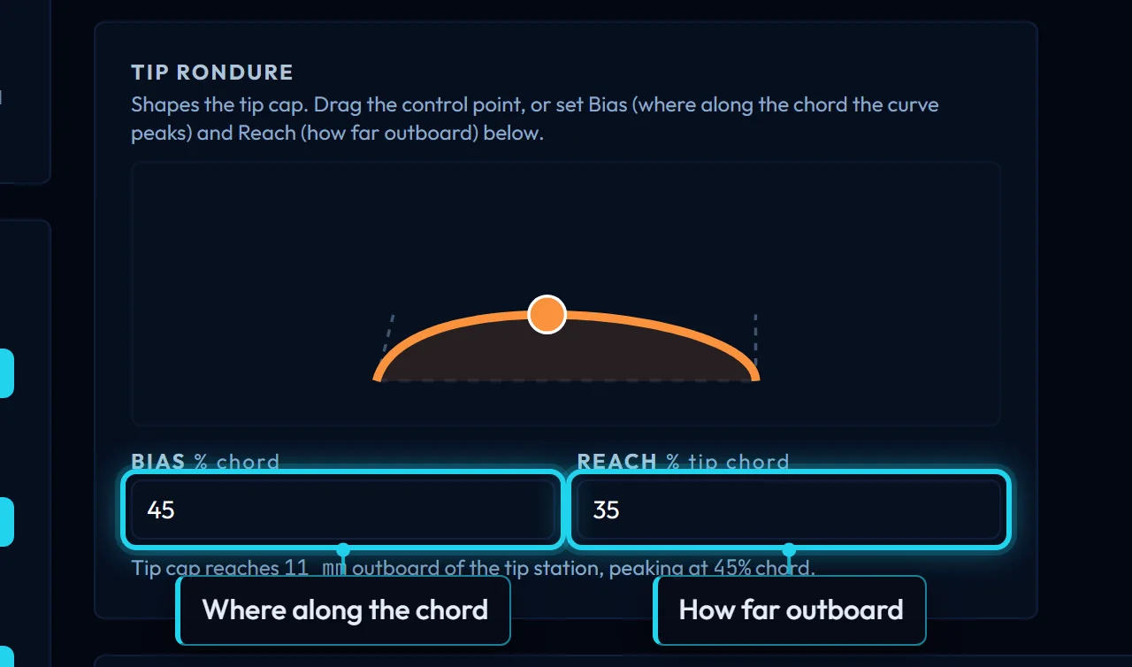
- The tip rondure rounds the end of the planform; Reach is how far the cap runs past the last station. The export carries the same cap.
Dihedral
Dihedral is the angle of the tip above the root, -20 to 30°; negative is anhedral, the tips below. It sets the end of the front-view curve, and points on that curve shape the path between: a polyhedral glider breaks upward part-way out, a hydrofoil droops smoothly. On an aircraft, dihedral is the roll stability that brings a wing level after a gust. On a hydrofoil the sign is usually negative, -2° on the example: tips below the fuselage keep the span working as the board heels and let a turn start from a lean, and a tip that climbs toward the surface ventilates. The analyses on this site are steady and rigid and do not model roll, so dihedral moves their numbers very little; its reasons are handling, not drag.
The tip rondure
The tip station is the last section the loft passes through. Left alone it would end as a flat cut; the rondure closes it with a rounded cap that continues the leading and trailing edges past the tip rather than kinking off them. The cap's outline is a cubic curve whose end tangents are the two edges' slopes at the tip, and two numbers set what is left free.
Reach is how far the cap extends past the tip station, as a percentage of half the tip chord, 0 to 100: at 100 it reaches half a tip chord outboard, at 0 the tip is cut flat. The example's 35 % on a 62 mm chord is 11 mm. Bias is where along the chord the cap reaches furthest out, as a percentage from the leading edge, 5 to 95, default 45. Staying tangent to the edges limits how far the peak can travel; the readout under the preview says where it landed, and the preview's control point drags both at once. The export draws the same cap from the same numbers.
What each control moves
An effects table will show what a step of twist and of dihedral does to two reference wings, a hydrofoil in salt water and an RC wing in air: (L/D)max, drag at the cruise point, span efficiency and where the stall starts. Expect dihedral to move almost nothing, for the reason above, and twist to move the stall station first.
| Wing | Change | (L/D) max | CD at cruise | Span efficiency e | First stall η |
|---|---|---|---|---|---|
| Wing Foil — Freeride | Baseline | 29.6 | 0.0110 | 0.82 | 0.72 |
| Wing Foil — Freeride | Half-span +10% | +2.3% | −10.6% | ||
| Wing Foil — Freeride | Half-span −10% | −4.0% | +15.9% | ||
| Wing Foil — Freeride | Root chord +10% | −2.2% | −4.2% | ||
| Wing Foil — Freeride | Root chord −10% | +2.0% | +5.1% | −0.6% | −0.13 |
| Wing Foil — Freeride | Tip chord +10% | −0.9% | −1.7% | −0.06 | |
| Wing Foil — Freeride | Tip chord −10% | +0.8% | +1.8% | ||
| Wing Foil — Freeride | Sweep +5° | +1.2% | −0.5% | ||
| Wing Foil — Freeride | Sweep −5° | −1.0% | −0.69 | ||
| Wing Foil — Freeride | Tip twist +1° | ||||
| Wing Foil — Freeride | Tip twist −1° | −0.06 | |||
| Wing Foil — Freeride | Dihedral +2° | ||||
| Wing Foil — Freeride | Dihedral −2° | ||||
| RC Trainer | Baseline | 20.3 | 0.0280 | 0.80 | 0.03 |
| RC Trainer | Half-span +10% | +3.2% | −16.5% | ||
| RC Trainer | Half-span −10% | −3.3% | +24.4% | ||
| RC Trainer | Root chord +10% | −0.9% | −4.8% | +1.0% | |
| RC Trainer | Root chord −10% | +1.1% | +5.8% | −1.8% | |
| RC Trainer | Tip chord +10% | −1.8% | −3.7% | −0.8% | |
| RC Trainer | Tip chord −10% | +2.2% | +4.2% | ||
| RC Trainer | Sweep +5° | −0.9% | |||
| RC Trainer | Sweep −5° | ||||
| RC Trainer | Tip twist +1° | ||||
| RC Trainer | Tip twist −1° | ||||
| RC Trainer | Dihedral +2° | ||||
| RC Trainer | Dihedral −2° |
Source: pyfoil ac7e53e /analyze-wing, AeroBuildup, constant-lift sweep 4–30 m/s in 1 m/s steps, 20 stations, NeuralFoil small, run 2026-11-11 on a local pyfoil. Wing Foil — Freeride (template wing-foil-freeride; n63412; half-span 500 mm, chords 145/62 mm, sweep 9.675 (quarter-chord 5.0°), dihedral -2°, tip twist -2°) at 95 kg and 7 m/s in water (sea) (ρ 1025, μ 0.00108). RC Trainer (template rc-trainer; clarky; half-span 700 mm, chords 250/250 mm, sweep 0 (quarter-chord 0.0°), dihedral 3°, tip twist 0°) at 2.5 kg and 15 m/s in air (ρ 1.225, μ 0.00001789). (L/D) max is the best feasible row of the sweep; CD at cruise is the row at the template's speed; e and the first-stall station η (fraction of the half-span, from stall_progression) are pyfoil's summary at its best-L/D row. Each change is one designer control moved from the baseline (lengths ±10%, angles as absolute steps); the cells are the change relative to the baseline row, and anything under 0.5% (0.005 of the half-span for η) is left blank. η is where the stall margin is lowest; across the span that margin varies by 2% on the Wing Foil — Freeride and 18% on the RC Trainer, and where it is nearly flat a small change moves η a long way without meaning much.
What this hands on
The twist and dihedral curves and the tip cap are saved with the design. The analysis reads the twist at each station and reports where the stall starts, the check that says whether the washout was needed; the export lofts the rotated, lifted stations and closes them with the cap.
Controls on this page
| Control | What it does | Units |
|---|---|---|
| Root | The section at the centreline. Type to search the library. With no tip section it is the whole wing; the viewer, the analysis and the export all draw from the same CST parameters. | |
| Tip | The section at the tip. Leave it empty and the tip is the root section. Set it and every station between is blended from root to tip, in the viewer, the analysis and the export alike. | |
| Re ≈ | The Reynolds number at this section, from its own chord, the operating speed and the fluid: Re = ρVc/μ. The tip, with a shorter chord, flies at a lower Re than the root; read each section's polars there. | |
| Find → | Opens Mission with this slot's Reynolds number and the design CL already filled in, so the selector ranks sections for exactly this station. Its results offer "Apply to root" or "Apply to tip". | |
| Optimize → | Opens Optimize starting from this slot's section at its Reynolds number and CL. The optimized shape comes back to the same slot. Needs a section in the slot first. | |
| Operating conditions | Speed, fluid and design lift coefficient. They set the Re ≈ beside each section and what Find → and Optimize → ask for. Set them on Mission, or load a reference design, which carries its own. | |
| Full span | Twice the half-span: the whole wing, tip to tip. Every length you type is for one half; the derived figures and the export are for both. | mm |
| Planform area | Both halves, integrated from the drawn leading and trailing edges at 40 stations, not from a trapezoid, so a curved outline counts. It is the S_ref the analysis reports. | m² |
| Aspect ratio | Full span squared over planform area. Higher means less induced drag for the same lift and a heavier root bending load; a glider is 20 and up, a freeride foil about 9. | |
| Taper ratio | Tip chord over root chord, λ. About 0.35 comes closest to an elliptical span loading on a straight wing; below that the tip loads up and wants washout. | |
| Sweep ¼c | The real quarter-chord sweep, measured off the planform the Sweep control built: the angle of the root-to-tip line through each chord's quarter point. This is the Λ a textbook or XFLR5 means. | deg |
| Sweep LE | The real leading-edge sweep: the angle of the straight line from the root leading edge to the tip leading edge. Larger than Λ¼c on a tapered wing, because the taper rakes the LE back. | deg |
| MAC | Mean aerodynamic chord, ∫c² dy / S over the half-wing. The reference length for Reynolds number at the wing level, for pitching moment and for the static margin. | mm |
| MAC spanwise | How far out from the centreline the mean aerodynamic chord sits. Where the half-wing's lift acts, near enough, so it is the arm the root bending moment works on. | mm |
| Wing loading | Weight over planform area, in pascals, at two fixed masses: 25 kg (a large RC model or a child on a foil) and 85 kg (an adult rider). Divide by ½ρV² for the lift coefficient the wing must fly at. | Pa |
| Target area | Scales the whole wing uniformly to this planform area: span and chords by the same factor, so aspect ratio, taper and the spline shape are unchanged. | m² |
| Target AR, hold area | Reaches this aspect ratio without changing the area: span grows by √(new/current) and every chord shrinks by the same factor. Exact for a curved outline, because it works on ratios. | |
| Target AR, hold span | Reaches this aspect ratio without changing the span: every chord is scaled by current/new AR, so the area moves instead. | |
| Standard series | Eight textbook planforms, each built at the span and aspect ratio you type. λ is taper ratio, AR aspect ratio, Λ the true quarter-chord sweep. Applying one changes the shape only; sections and operating point stay. | |
| Reference designs | 15 complete wings at real sizes, from a surf foil to a bizjet. Loading one replaces everything: planform, sections, tip cap, export settings and the speed, fluid, CL and mass it was sized for. | |
| LE and TE points | Add a point to the leading or trailing edge and drag it: the edge becomes a smooth curve through every point. Diamonds at root and tip set the end tangents; the root one is locked level so the two halves meet without a kink. | |
| Half-span | Centreline to tip, for one half; the wing is mirrored about the root. 100 to 20,000 mm. Interior points keep their position in mm, so lengthen the span and they stay where they were. | mm |
| Root chord | Leading edge to trailing edge at the centreline, 10 to 5,000 mm. Sets the root section's Reynolds number and, with the tip chord, the taper ratio. | mm |
| Tip chord | Chord at the tip station, from 1 mm. A shorter tip means a lower Reynolds number there and, with no twist, a tip that loads up; the tip rondure's reach is a fraction of it. | mm |
| Sweep | Where the tip leading edge lands: tan(sweep) × half-span, minus a quarter of the taper. It is not the quarter-chord or the leading-edge sweep; the real angles it produces are under Derived Parameters. | deg |
| Dihedral | Angle of the tip above the root, -20 to 30°; negative is anhedral, the tips below the root. Sets the end of the front-view curve; points on that curve shape the path between. | deg |
| Tip twist | Geometric angle of the tip section relative to the root, -15 to 10°. Negative is washout: the tip flies at a lower angle and stalls after the root. The profile between is the twist curve. | deg |
| Bias | Where along the tip chord the rounded cap reaches furthest out, as a percentage from the leading edge, 5 to 95. Tangency to the edges limits the range; the readout says where the peak actually landed. | % chord |
| Reach | How far the cap extends past the tip station, as a percentage of half the tip chord: at 100 it reaches half a tip chord outboard; at 0 the tip is cut flat. The export carries the same cap. | % tip chord |
| Loft sections | How many stations the exporter lofts through between root and tip, 10 to 80, default 30. More follows a curved edge or a twist profile more closely and takes longer to build. | |
| TE thickness | Opens every station's trailing edge to at least this, up to 10 mm, for a cutter or a printer that cannot make a knife edge. 0 keeps each section's own edge. The viewer always shows the section as drawn. | mm |
| Format | STEP is the exact lofted solid for CAD: shell it, split it, cut moulds from it. STL is the same solid as a triangle mesh for slicers and mesh tools. Both are in millimetres and hold both halves. | |
| Generate 3D wing | Builds the solid in CAD on the server and downloads it, usually in under 20 s; it stops at 90 s and says why. Needs a sign-in and a root section. The file is the same loft the viewer shows. | |
| 3D preview | The wing lofted live from the controls, both halves. Seven camera views on keys 1–7, Ortho or Persp on O, the ground grid on G, Expand on E. Drag to orbit, scroll to zoom, right-drag to pan. | |
| Shading | Solid shows the surface as a painted composite would read. Solid+wire adds the station rings and the leading, trailing and quarter-chord lines over it. Wires shows only those, so the loft is visible through the wing. | |
| Tail area | Stabiliser planform area, both sides together, in m². With the arm it sets the tail volume V_H; the cm² echo under the inputs is for foil builders, who size in cm². | m² |
| Tail arm | From the wing's quarter chord at its MAC to the stabiliser's quarter chord at its MAC, in mm. On a hydrofoil it is roughly the fuselage length. | mm |
| Tail AR | Stabiliser aspect ratio, span² over area. It sets how much lift the tail makes per degree. 3–5 is the band the card calls responsive without stalling before the wing. | |
| CG | Centre of gravity as a fraction of the wing MAC, measured aft of the MAC leading edge. 0.25 is the wing's own aerodynamic centre; the static margin is how far the neutral point sits behind this. | × MAC |
| Tail volume | V_H = S_h · l_h / (S · MAC): the tail's area times its arm, scaled by the wing's. The one number that says how much authority the tail has; the card shows where it sits among the site's rigs. | |
| Neutral point | Stick-fixed neutral point of wing plus tail, as a fraction of MAC and in mm: the CG position at which the rig would be neutrally stable. No fuselage; one moves it forward by about 0.05–0.10 MAC. | |
| Static margin | Neutral point minus CG, as a percentage of MAC. Positive is statically stable: a nose-up disturbance makes a nose-down moment. Larger is steadier and needs more stabiliser trim to fly level. | % MAC |
| Estimate terms | The four factors the neutral point is built from: area ratio S_h/S, arm in chords l_h/MAC, the tail's lift slope over the wing's, and 1 − dε/dα, how much of the wing's downwash the tail sits in. |